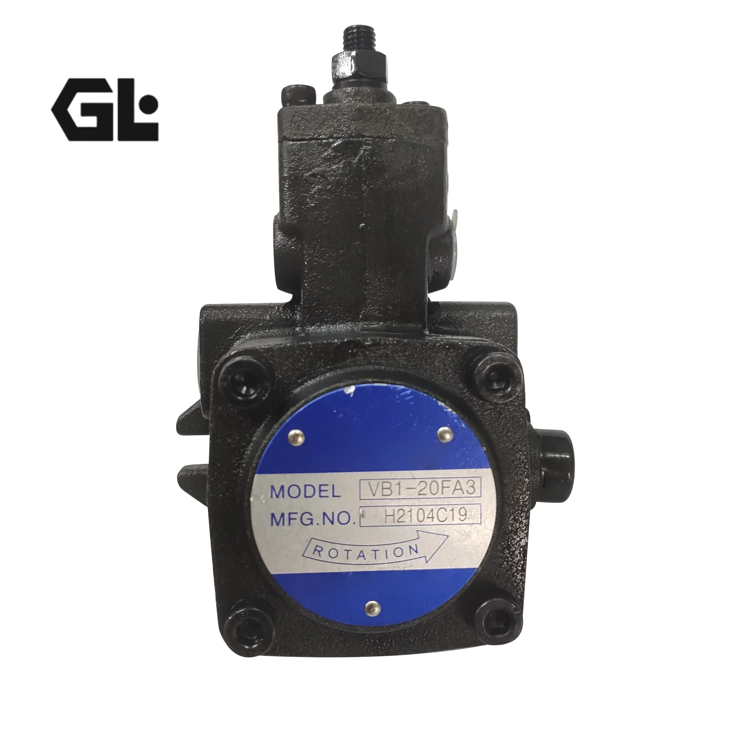
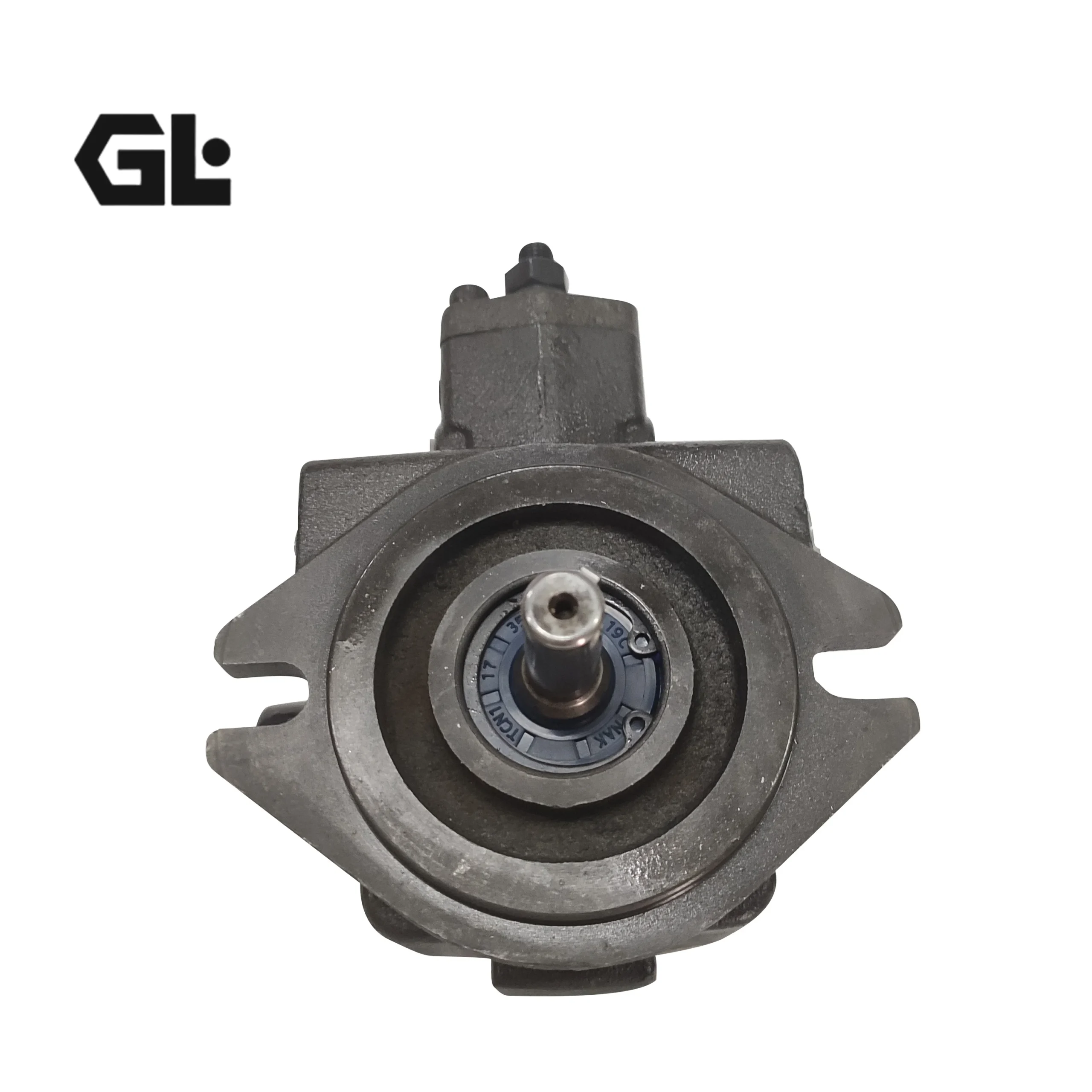
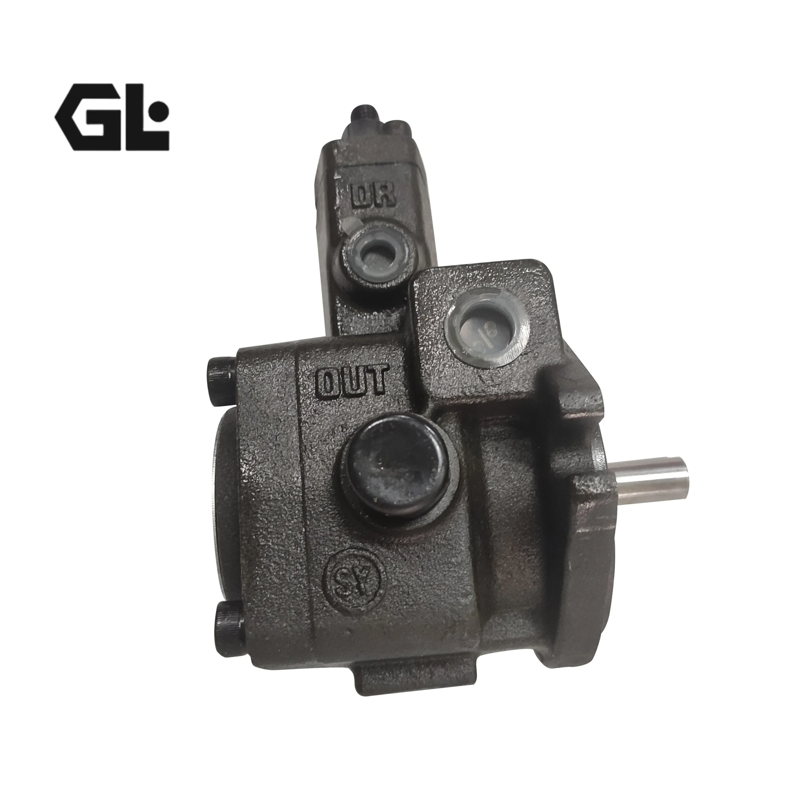
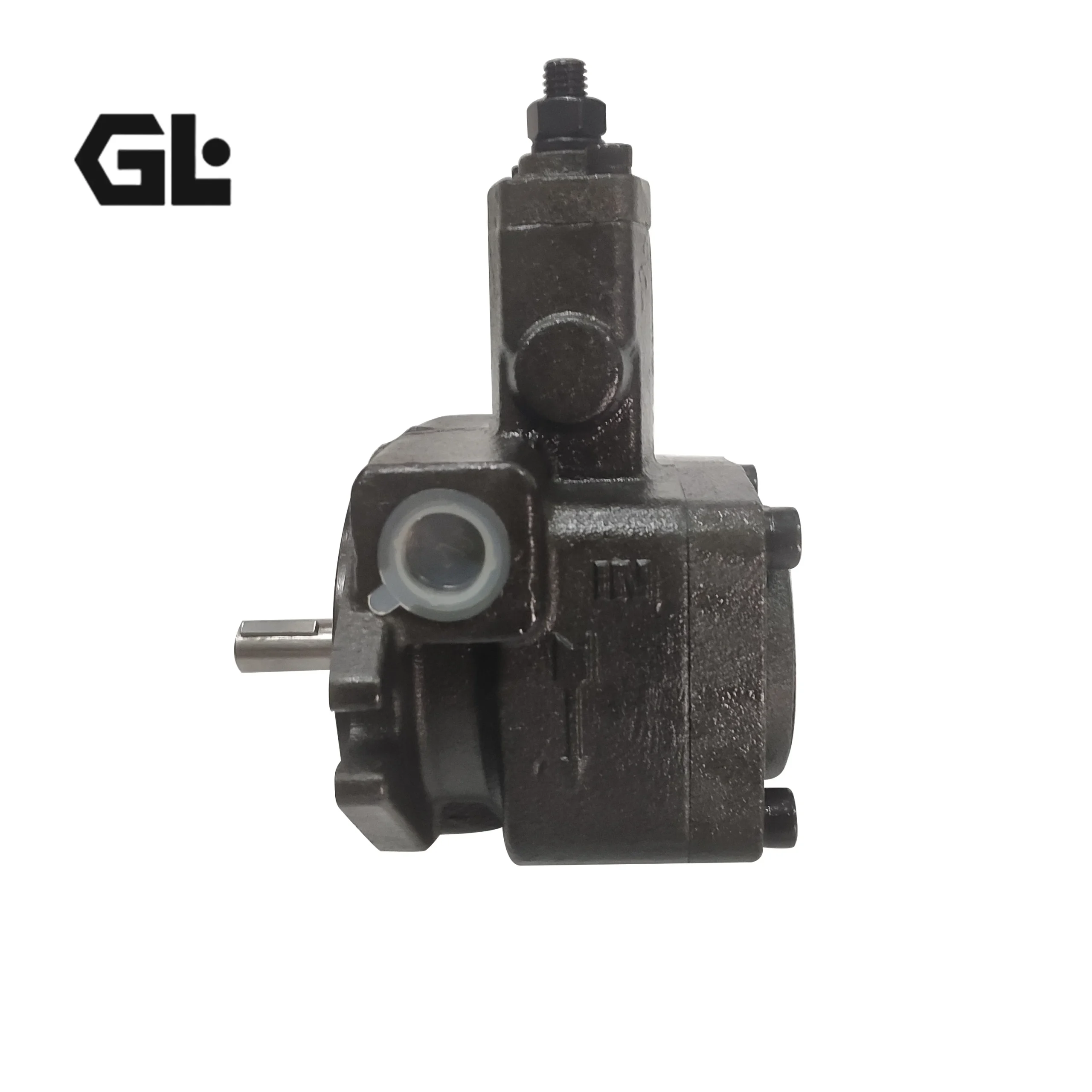
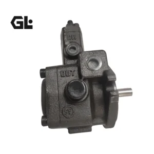

Product Overview
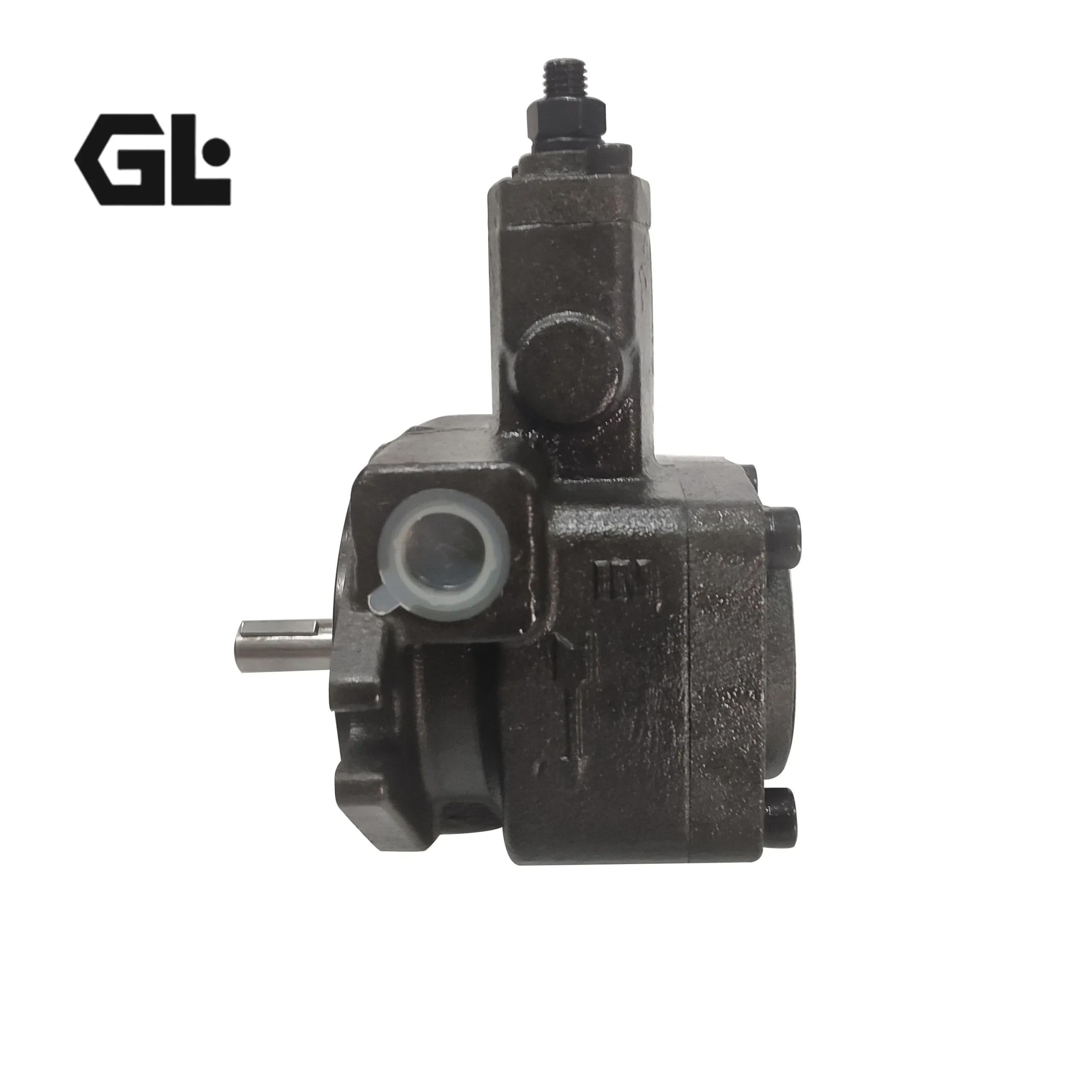
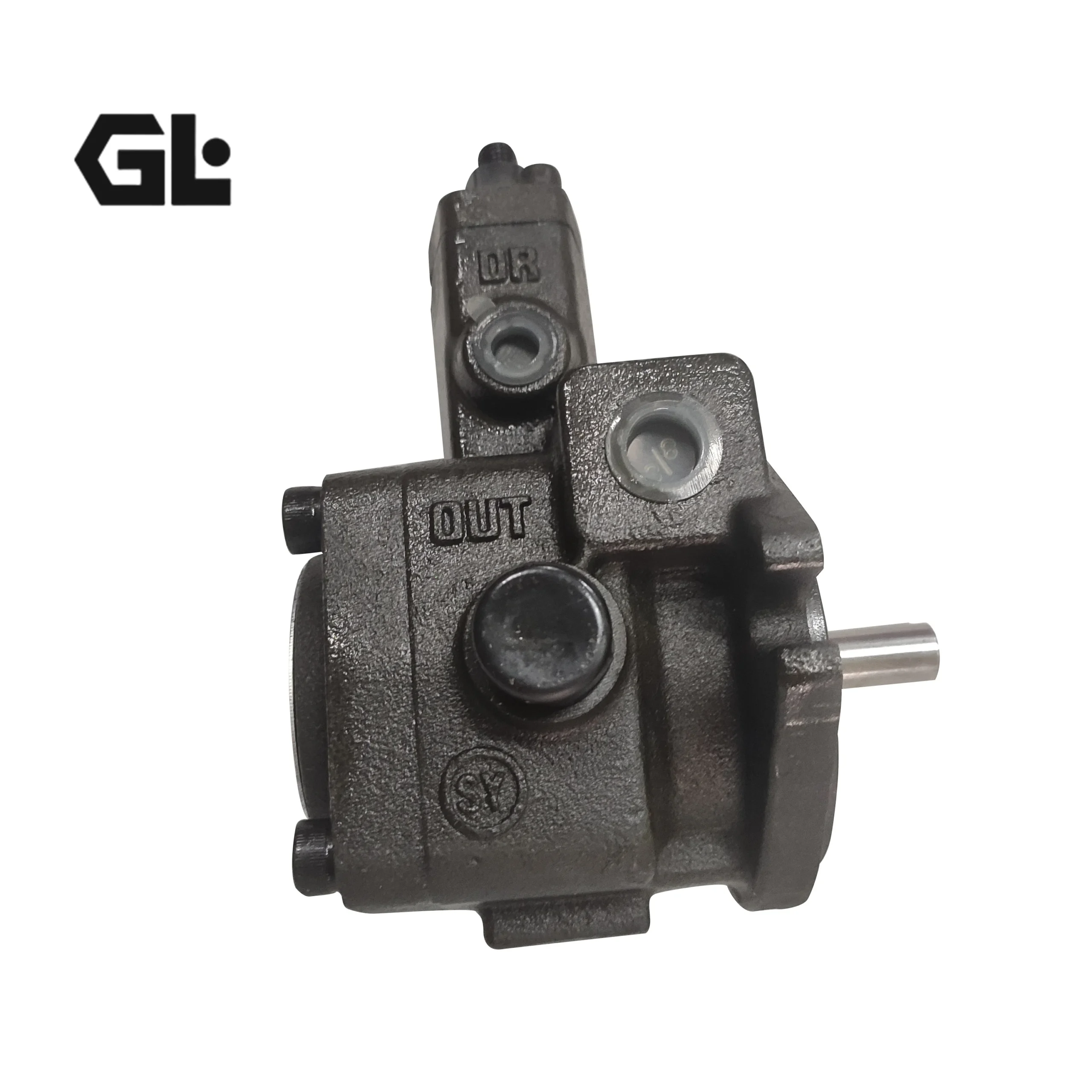
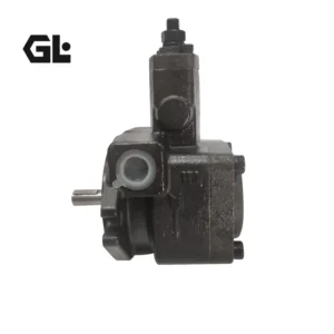
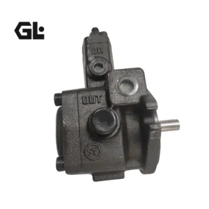
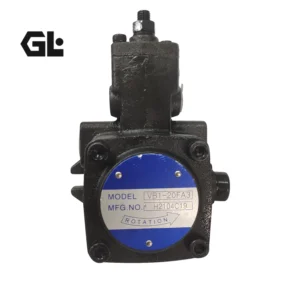
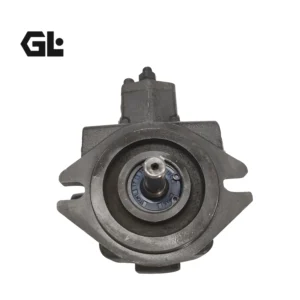
The VB1-20F-A3 (low-pressure variable pump), VE2-40FA4 (medium-pressure variable pump), and VP-20F/A3 (general-purpose variable pump) belong to the KOMPASS (朝田) variable displacement vane pump platform — one of the most widely installed low/medium-pressure vane pump platforms in global industrial hydraulics. The KOMPASS VA1/VB1/VC1/VD1/VE1 series (7 MPa), VD2/VE2/VF2/VK2 series (14 MPa), and VP series collectively serve machine tools, automation equipment, shoe-making machinery, and special-purpose machines worldwide.
The VB1-20F-A3 is a VB1-frame low-pressure variable displacement pump with a geometric displacement of 11.1 cm³/rev, delivering a rated output flow of 20 L/min at 1800 rpm (no-load). Maximum operating pressure is 7 MPa (70 kgf/cm²), with A3 pressure adjustment range of 3.0-7.0 MPa (30-70 kgf/cm²). It features flange mounting (F-type) and clockwise rotation (viewed from shaft end). The pump employs KOMPASS’s patented “shaft clearance compensation” design that automatically adjusts pump displacement according to set pressure, with a built-in pressure adjustment valve eliminating the need for external relief valves.
The VE2-40FA4 is a VE2-frame medium-pressure variable displacement pump with a geometric displacement of 22.2 cm³/rev, delivering a rated output flow of 40 L/min at 1800 rpm (no-load). Maximum operating pressure is 14 MPa (140 kgf/cm²), with A4 pressure adjustment range of 7.0-14.0 MPa (70-140 kgf/cm²). This pump doubles the pressure capability of the VB1 series, serving medium-to-high pressure hydraulic circuits.
The VP-20F/A3 is a VP-series general-purpose variable displacement pump with identical displacement (11.1 cm³/rev) and flow output (20 L/min @ 1800 rpm) to the VB1-20F-A3, offering the same 7 MPa maximum pressure with A3 pressure range. The VP series shares the same core engineering principles but differs in external dimensions and mounting interfaces to accommodate different equipment platforms.
All three models feature drop-in interchangeability with original KOMPASS specifications, compatibility with Toyooki HVP series and domestic VP series equivalents, 100% factory testing, built-in pressure adjustment, and direct motor coupling capability.
Technical Specifications
Model VB1-20F-A3 (Low-Pressure Variable Pump):
- Pump Series: VB1 Low-Pressure Variable Displacement Vane Pump (KOMPASS)
- Frame Size: VB1
- Displacement Code: 20
- Geometric Displacement: 11.1 cm³/rev (0.68 in³/rev)
- Rated Output Flow (@1500 rpm, no-load): 16.7 L/min
- Rated Output Flow (@1800 rpm, no-load): 20 L/min
- Maximum Operating Pressure: 7 MPa (70 kgf/cm²)
- Pressure Range Code: A3
- Pressure Adjustment Range: 3.0-7.0 MPa (30-70 kgf/cm²)
- Maximum Peak Pressure: 14 MPa (140 kgf/cm², instantaneous, must not exceed)
- Maximum Speed: 1800 rpm
- Minimum Stable Speed: 800 rpm
- Control Type: Pressure-compensated variable displacement (limiting pressure type)
- Rotation: Clockwise (viewed from shaft end), only this direction
- Shaft Type: Standard straight shaft with key
- Mounting: F-type Flange mounting
- Outlet Port Size: 3/8″ PT
- Inlet Port Size: 1/2″ PT
- Drain Port Size: 1/4″ PT
- Hydraulic Fluid (below 7 MPa): 20-50 cSt at 40°C (ISO VG 32)
- Operating Oil Temperature: 15-60°C (continuous operation)
- Case Drain Backpressure: ≤0.03 MPa (drain line must connect directly below oil surface)
- Suction Port Pressure: -0.03 MPa to +0.03 MPa
- Shaft Alignment: Eccentricity ≤0.05 mm, angular error ≤1°
- Weight (Flange type): 5.5 kg
- Weight (Foot type): 6.5 kg
- Housing Material: High-strength cast iron
- Seal Material: NBR (standard)
Model VE2-40FA4 (Medium-Pressure Variable Pump):
- Pump Series: VE2 Medium-Pressure Variable Displacement Vane Pump (KOMPASS)
- Frame Size: VE2
- Displacement Code: 40
- Geometric Displacement: 22.2 cm³/rev (1.35 in³/rev)
- Rated Output Flow (@1500 rpm, no-load): 33.3 L/min
- Rated Output Flow (@1800 rpm, no-load): 40 L/min
- Maximum Operating Pressure: 14 MPa (140 kgf/cm²)
- Pressure Range Code: A4
- Pressure Adjustment Range: 7.0-14.0 MPa (70-140 kgf/cm²)
- Maximum Peak Pressure: 14 MPa (140 kgf/cm²)
- Maximum Speed: 1800 rpm
- Minimum Stable Speed: 800 rpm
- Control Type: Pressure-compensated variable displacement (limiting pressure type)
- Rotation: Clockwise (viewed from shaft end), only this direction
- Shaft Type: Standard straight shaft with key
- Mounting: F-type Flange mounting
- Outlet Port Size: 1/2″ PT
- Inlet Port Size: 3/4″ PT
- Drain Port Size: 1/4″ PT
- Hydraulic Fluid (below 7 MPa): 20-50 cSt at 40°C (ISO VG 32)
- Hydraulic Fluid (above 7 MPa): 30-68 cSt at 40°C (ISO VG 46/VG 68)
- Operating Oil Temperature: 15-60°C (continuous operation)
- Case Drain Backpressure: ≤0.03 MPa (drain line must connect directly below oil surface)
- Suction Port Pressure: -0.03 MPa to +0.03 MPa
- Shaft Alignment: Eccentricity ≤0.05 mm, angular error ≤1°
- Weight (Flange type): 10 kg
- Weight (Foot type): 13 kg
- Housing Material: High-strength thickened cast iron
- Seal Material: NBR (standard)
Model VP-20F/A3 (General-Purpose Variable Pump):
- Pump Series: VP General-Purpose Variable Displacement Vane Pump
- Displacement Code: 20
- Geometric Displacement: 11.1 cm³/rev (0.68 in³/rev)
- Rated Output Flow (@1500 rpm, no-load): 16.7 L/min
- Rated Output Flow (@1800 rpm, no-load): 20 L/min
- Maximum Operating Pressure: 7 MPa (70 kgf/cm²)
- Pressure Range Code: A3
- Pressure Adjustment Range: 3.0-7.0 MPa (30-70 kgf/cm²)
- Maximum Peak Pressure: 14 MPa (140 kgf/cm², instantaneous, must not exceed)
- Maximum Speed: 1800 rpm
- Minimum Stable Speed: 800 rpm
- Control Type: Pressure-compensated variable displacement (limiting pressure type)
- Rotation: Clockwise (viewed from shaft end)
- Shaft Type: Standard straight shaft with key, shaft diameter φ12.7 mm (1/2″), keyway 3.175 mm
- Mounting: F-type Flange mounting
- Outlet Port Size: 3/8″ PT
- Inlet Port Size: 1/2″ PT
- Drain Port Size: 1/4″ PT
- Hydraulic Fluid: 30-50 cSt at 40°C (ISO VG 32)
- Operating Oil Temperature: 15-60°C (continuous operation)
- Case Drain Backpressure: ≤0.3 bar (drain line must connect directly below oil surface)
- Suction Port Pressure: -0.3 bar to +0.3 bar
- Shaft Alignment: Eccentricity ≤0.05 mm, angular error ≤1°
- Weight (Flange type): 5.5 kg
- Housing Material: High-strength cast iron
- Seal Material: NBR (standard)
Key Technical Advantages
1. “Shaft Clearance Compensation” Design — Stable Performance Under Continuous High-Pressure Operation
KOMPASS variable vane pumps employ a proprietary “shaft clearance compensation” mechanism that automatically compensates for axial clearance between the rotor end face and the distributor plate through hydraulic feedback force. When the pump operates continuously under high pressure, any increased clearance due to end-face wear is automatically compensated, ensuring volumetric efficiency remains at a high level throughout the pump’s service life. This design fundamentally resolves the pain point of traditional variable vane pumps — increased internal leakage and pressure drop caused by end-face wear during prolonged high-pressure operation — forming the core engineering basis for KOMPASS pumps’ long service life and high efficiency.
KOMPASS variable vane pumps employ a proprietary “shaft clearance compensation” mechanism that automatically compensates for axial clearance between the rotor end face and the distributor plate through hydraulic feedback force. When the pump operates continuously under high pressure, any increased clearance due to end-face wear is automatically compensated, ensuring volumetric efficiency remains at a high level throughout the pump’s service life. This design fundamentally resolves the pain point of traditional variable vane pumps — increased internal leakage and pressure drop caused by end-face wear during prolonged high-pressure operation — forming the core engineering basis for KOMPASS pumps’ long service life and high efficiency.
2. Eccentric Piston Control Mechanism — Fast Response, Sensitive Action
KOMPASS variable vane pumps utilize an eccentric piston as the pressure feedback control element, replacing conventional spring-piston mechanisms. The eccentric piston delivers extremely fast response speeds, rapidly adjusting the cam ring’s eccentricity during transient conditions such as start-up, stop, and sudden load changes. Unlike spring-loaded variable mechanisms, the eccentric piston control eliminates spring fatigue failure risk, provides high pressure adjustment stability, and ensures fast response — guaranteeing pressure stability in precision hydraulic systems under dynamic operating conditions.
KOMPASS variable vane pumps utilize an eccentric piston as the pressure feedback control element, replacing conventional spring-piston mechanisms. The eccentric piston delivers extremely fast response speeds, rapidly adjusting the cam ring’s eccentricity during transient conditions such as start-up, stop, and sudden load changes. Unlike spring-loaded variable mechanisms, the eccentric piston control eliminates spring fatigue failure risk, provides high pressure adjustment stability, and ensures fast response — guaranteeing pressure stability in precision hydraulic systems under dynamic operating conditions.
3. Built-In Pressure Adjustment Valve — System Simplification & Cost Savings
KOMPASS variable vane pumps incorporate a high-precision built-in pressure adjustment valve, eliminating the need for external relief valves or pressure-reducing valves. When system pressure reaches the set point, the pump automatically reduces output flow to a minimum compensation level, achieving “unload-on-pressure” energy savings. Compared to fixed displacement pump + relief valve systems, power consumption during high-pressure, low-flow conditions is significantly reduced, and fluid heating is minimized. This design not only simplifies system piping but also reduces system cost and potential failure points.
KOMPASS variable vane pumps incorporate a high-precision built-in pressure adjustment valve, eliminating the need for external relief valves or pressure-reducing valves. When system pressure reaches the set point, the pump automatically reduces output flow to a minimum compensation level, achieving “unload-on-pressure” energy savings. Compared to fixed displacement pump + relief valve systems, power consumption during high-pressure, low-flow conditions is significantly reduced, and fluid heating is minimized. This design not only simplifies system piping but also reduces system cost and potential failure points.
4. Direct Motor Coupling Design — Compact & Efficient
KOMPASS variable vane pumps feature a compact structural design that allows direct coupling with standard electric motors via flexible couplings to form motor-pump units, without the need for additional transmission mechanisms or reduction gears. Both flange mounting (F-type) and foot mounting (L-type) configurations provide flexible adaptation to different equipment platforms. Shaft alignment requirements are limited to 0.05 mm eccentricity and 1° angular error, making assembly straightforward and significantly saving installation space.
KOMPASS variable vane pumps feature a compact structural design that allows direct coupling with standard electric motors via flexible couplings to form motor-pump units, without the need for additional transmission mechanisms or reduction gears. Both flange mounting (F-type) and foot mounting (L-type) configurations provide flexible adaptation to different equipment platforms. Shaft alignment requirements are limited to 0.05 mm eccentricity and 1° angular error, making assembly straightforward and significantly saving installation space.
5. High-Order Non-Impact Transition Curve Cam Ring — Low Noise, Long Life
KOMPASS variable vane pumps feature cam rings with advanced high-order non-impact transition curves machined into the inner surface, ensuring optimal vane motion and force distribution during the suction-to-discharge transition. The contact force between vane tips and the cam ring surface changes smoothly without sudden variations, effectively reducing contact stress and wear between vanes and the cam ring. This ensures reliable sealing contact while minimizing flow losses, pressure pulsation, and flow pulsation — resulting in low operating noise and extended service life.
KOMPASS variable vane pumps feature cam rings with advanced high-order non-impact transition curves machined into the inner surface, ensuring optimal vane motion and force distribution during the suction-to-discharge transition. The contact force between vane tips and the cam ring surface changes smoothly without sudden variations, effectively reducing contact stress and wear between vanes and the cam ring. This ensures reliable sealing contact while minimizing flow losses, pressure pulsation, and flow pulsation — resulting in low operating noise and extended service life.
6. Medium-Pressure VE2 Series — Double Pressure for Broader Application Coverage
The VE2 series variable vane pumps double the maximum operating pressure from 7 MPa (VB1 series) to 14 MPa (140 kgf/cm²), with A4 pressure adjustment range covering 7.0-14.0 MPa. This enables the VE2 series to serve a wider range of medium-to-high pressure industrial hydraulic systems, including medium-sized hydraulic presses, injection molding clamp circuits, and die-casting auxiliary circuits. The VE2 series features a thickened cast iron housing with significantly enhanced structural strength, ensuring safe and reliable operation under 14 MPa high-pressure conditions.
The VE2 series variable vane pumps double the maximum operating pressure from 7 MPa (VB1 series) to 14 MPa (140 kgf/cm²), with A4 pressure adjustment range covering 7.0-14.0 MPa. This enables the VE2 series to serve a wider range of medium-to-high pressure industrial hydraulic systems, including medium-sized hydraulic presses, injection molding clamp circuits, and die-casting auxiliary circuits. The VE2 series features a thickened cast iron housing with significantly enhanced structural strength, ensuring safe and reliable operation under 14 MPa high-pressure conditions.
Application Areas
- Machine Tool Hydraulics: Clamping, feed, and lubrication circuits on CNC machining centers, lathes, grinders, and drilling machines; low-noise characteristics ideal for precision machining workshops
- Automatic Lathes & Swiss-Type Lathes: Bar feed, tool clamping, and tailstock circuits; variable displacement enables automatic switching between rapid feed and precision holding pressure
- Shoe-Making Machinery: Hydraulic drives for sole pressing machines, cutting presses, and setting machines
- Grinding & Polishing Machines: Workpiece clamping and table feed hydraulic circuits
- Industrial Power Units (HPU): Central hydraulic power sources where variable displacement effectively reduces standby energy consumption
- Hydraulic Presses: Stamping, bending, and deep drawing press main drive circuits (VE2 series for 14 MPa applications)
- Injection Molding Machines: Clamp, mold-adjustment, and ejector circuits for small-to-medium machines (VE2 series)
- Packaging & Woodworking Machinery: Hydraulic balers, panel saws, and edge banders
Expert Maintenance Tips
- Fluid Cleanliness Control: Maintain system fluid cleanliness at ISO 4406 18/16/13 or better. Install a 100–150 mesh suction strainer and a 10μm return-line filter. Contaminated fluid is the leading cause of abnormal vane wear and cam ring scoring.
- Viscosity & Temperature Management: For pressures below 7 MPa, use hydraulic oil with viscosity of 20–50 cSt at 40°C (ISO VG 32); for pressures above 7 MPa (VE2 series), use 30–68 cSt at 40°C (ISO VG 46/VG 68). Maintain continuous operating oil temperature between 15–60°C. Perform a no-load warm-up cycle during cold starts to prevent cavitation from high-viscosity fluid.
- Case Drain Line Requirements: The case drain line must be piped directly to below the oil surface in the tank, and backpressure in the drain line must be maintained below 0.03 MPa (0.3 bar). Excessive drain backpressure increases internal leakage, reduces volumetric efficiency, and may cause shaft seal failure. The drain line must never be merged with other return lines or fitted with throttling valves.
- Shaft Alignment & Coupling Selection: Maintain shaft misalignment within 0.05 mm and angular error within 1°. Use a flexible coupling to absorb installation errors and axial float. Never use rigid couplings, as radial side-loads will cause premature bearing failure.
- Suction Conditions: Maintain suction port pressure between -0.03 MPa and +0.03 MPa. Keep suction piping as short and large-diameter as possible — pipe bore must not be smaller than the pump suction port. Excessive suction line resistance causes cavitation.
- Initial Start-Up & Air Bleeding: During initial start-up, repeatedly start the electric motor under no-pressure conditions to expel air from the pump cavity and suction line. Once the pump is confirmed to be delivering oil, continue no-load operation for 10 minutes to ensure complete air removal before applying load. Never operate the pump dry — dry running will cause instant damage.
- Flow & Pressure Adjustment: To adjust flow, first loosen the lock nut, then turn the adjustment bolt — clockwise (right) to reduce flow, counter-clockwise (left) to increase. After adjustment, tighten the lock nut. For pressure adjustment: clockwise (right) increases output pressure, counter-clockwise (left) decreases it. After adjustment, tighten the lock nut.
- VE2 Series Specific Maintenance: The VE2 series operates at maximum pressures up to 14 MPa, requiring stricter fluid cleanliness and viscosity control. For pressures above 7 MPa, ISO VG 46 or VG 68 hydraulic oil is mandatory to ensure adequate oil film strength and lubrication performance under high-pressure conditions. Periodically check housing fastening bolt torque to prevent micro-leakage under high-pressure operation.